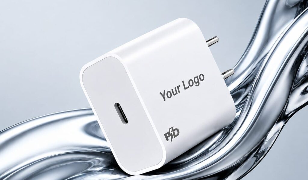
A mobile charger may look like a simple device, but it contains several electronic components that work together to convert electrical power into a safe and usable form for your smartphone, tablet, earbuds, and other devices.
Modern chargers are designed to deliver the required voltage and current while protecting both the charger and connected device from electrical problems. Understanding the main components of a mobile charger is useful for consumers, retailers, distributors, and businesses involved in mobile accessories manufacturing and sourcing.
In this complete guide, we will explain the major components inside a mobile charger, their functions, safety features, and how they work together.
What Is a Mobile Charger?
A mobile charger is an electronic power supply that converts electricity from an AC power outlet into regulated DC power suitable for charging electronic devices.
A typical wall charger receives AC electricity from a household socket and converts it into a lower, controlled DC output through a series of electronic circuits.
For example, a charger may provide outputs such as:
- 5V standard USB charging
- 9V fast charging
- 12V or higher outputs for supported fast-charging protocols
- USB-C Power Delivery (PD) profiles
The actual voltage and current delivered depend on the charger’s design and the charging protocol supported by the connected device.
Main Components of a Mobile Charger
A modern mobile charger generally contains several important components. The exact design varies according to the charger’s power rating, size, charging technology, and safety requirements.
The major components include:
- AC input section
- Fuse
- EMI filter
- Rectifier
- Capacitors
- Switching controller
- Transformer
- Secondary-side rectifier
- Feedback circuit
- Output filtering components
- USB-A or USB-C port
- Protection circuits
- PCB (Printed Circuit Board)
Let’s understand each component in detail.
1. AC Input Section
The AC input section is where electrical power enters the charger from the wall socket.
Depending on the charger design, this section includes terminals, contacts, and protective components that allow mains electricity to enter the internal circuit safely.
The input section is designed to handle the specified mains voltage range and prepare the incoming power for conversion.
For chargers intended for different markets, the input specification may vary depending on local electrical standards.
2. Fuse
A fuse is an important safety component inside many charger designs.
Its primary purpose is to protect the charger from excessive current. If a serious fault causes the current to rise beyond a safe level, the fuse can open the circuit and help prevent further damage.
A properly selected fuse can provide protection against conditions such as:
- Overcurrent
- Certain internal short circuits
- Component failures
The fuse is therefore an important part of the charger’s overall electrical safety design.
3. EMI Filter
EMI stands for Electromagnetic Interference.
An EMI filter helps reduce unwanted electrical noise generated by the charger’s switching circuits and can also help prevent external electrical noise from interfering with the charger.
Common components used in filtering include:
- Inductors
- Common-mode chokes
- Capacitors
- Other filtering elements
Good EMI filtering helps a charger operate more reliably and supports compliance with applicable electromagnetic compatibility requirements.
4. Rectifier
The electricity coming from a household outlet is AC, while the charger’s internal electronic circuits generally require DC.
A rectifier converts the incoming AC voltage into DC.
A common design uses a bridge rectifier made from diodes. The rectified output is then processed by the charger’s switching circuit.
This conversion is one of the first major stages in the charger’s power-conversion process.
5. Capacitors
Capacitors are found in several sections of a charger and perform different functions.
They can help:
- Smooth rectified voltage
- Store electrical energy temporarily
- Reduce voltage fluctuations
- Filter high-frequency noise
- Stabilize output power
The primary-side capacitor and output-side capacitors have different roles because they operate in different parts of the circuit.
The selection of capacitor type, voltage rating, temperature rating, and capacitance is important for charger reliability.
6. Switching Controller
The switching controller is one of the key components in a modern switched-mode charger.
Instead of continuously reducing voltage like a traditional linear power supply, a switching charger rapidly switches electrical power through its circuit at high frequency.
The switching controller controls this process and helps regulate the amount of energy transferred through the transformer.
Modern charger ICs may integrate several functions into a single semiconductor device, helping manufacturers create smaller and more efficient chargers.
7. Transformer
The transformer is a critical component in many isolated mobile charger designs.
It performs two major functions:
- Transfers electrical energy from the primary side to the secondary side
- Provides electrical isolation between the input and output sections
High-frequency transformers used in switched-mode chargers can be much smaller than traditional low-frequency transformers.
Transformer design depends on factors such as:
- Output power
- Switching frequency
- Core material
- Winding design
- Insulation requirements
- Efficiency targets
This is one reason modern fast chargers can be significantly smaller than older charger designs.
8. Secondary-Side Rectifier
After energy is transferred through the transformer, the output still needs to be converted and conditioned into the required DC form.
A secondary-side rectifier performs this conversion.
Depending on the charger’s design, manufacturers may use conventional diodes or more efficient semiconductor solutions such as synchronous rectification.
Efficient rectification can help reduce power losses and heat generation.
9. Feedback Circuit
A feedback circuit monitors the charger’s output and communicates information back to the control section.
Its purpose is to help maintain a stable output under changing load conditions.
For example, when the connected device changes its power demand, the charger needs to adjust its switching behavior to maintain the appropriate output.
In isolated charger designs, feedback may use components such as an optocoupler to maintain isolation between primary and secondary circuits.
10. Output Filtering Components
The output stage commonly contains inductors, capacitors, and other filtering components.
These components help smooth the converted DC power and reduce unwanted electrical ripple and noise.
Good output filtering is important because the connected smartphone or accessory requires a stable power supply.
The quality and design of the output stage can have a significant effect on charger performance.
11. USB-A or USB-C Port
The charging port is the physical interface between the charger and the device.
Older and widely used chargers may feature USB-A ports, while many modern chargers use USB-C.
USB-C has become particularly important for fast charging because it supports modern charging and power-delivery standards when implemented correctly.
A charger may support different output capabilities depending on its internal design and protocol implementation.
12. Charging Protocol Controller
Fast chargers often include additional circuitry for communication between the charger and the connected device.
This allows the charger and device to determine an appropriate power level.
Depending on the product, supported technologies may include:
- USB Power Delivery (USB PD)
- Programmable Power Supply (PPS)
- Other proprietary or manufacturer-specific fast-charging technologies
The charger should only provide power profiles supported by the connected device and charging protocol.
13. Protection Circuits
Safety and protection circuits are essential in modern chargers.
Depending on the design, a charger may include protection against:
- Overvoltage
- Overcurrent
- Short circuit
- Overtemperature
- Excessive power
- Input abnormalities
These protections help reduce the risk of damage to the charger and connected equipment.
A well-designed charger combines electrical protection with appropriate component selection, thermal design, insulation, and mechanical construction.
14. PCB (Printed Circuit Board)
The PCB is the board on which many of the charger’s electronic components are mounted and electrically connected.
It provides the pathways required for current and signal transmission between components.
A charger PCB may contain:
- Integrated circuits
- Diodes
- Resistors
- Capacitors
- Inductors
- Transformers
- Protection components
- Connectors
PCB layout is especially important in high-voltage and high-frequency charger designs because designers need to maintain appropriate electrical clearances, manage heat, minimize noise, and separate different circuit sections.
15. Resistors
Resistors are small but important components used throughout charger circuits.
They can be used for:
- Current limiting
- Voltage sensing
- Biasing electronic components
- Feedback networks
- Protection functions
- Signal conditioning
Different resistors are selected according to their resistance value, power rating, voltage rating, and other electrical characteristics.
16. Diodes
Diodes allow current to flow primarily in one direction and are widely used in charger circuits.
They may be used for:
- AC-to-DC rectification
- Output rectification
- Protection
- Switching and control functions
The type of diode used depends on the circuit requirements, voltage, current, switching frequency, and efficiency target.
17. Inductors
Inductors are used for energy storage and filtering.
They can be found in:
- EMI filters
- Switching circuits
- Output filters
- Power-conversion stages
Together with capacitors, inductors can help reduce unwanted electrical noise and stabilize the power output.
How Does a Mobile Charger Work?
A simplified charging process can be understood in several stages.
Step 1: AC Power Enters the Charger
Electricity enters the charger through the AC input section.
Step 2: Input Protection and Filtering
The input circuit uses components such as a fuse and EMI filter to provide protection and reduce unwanted electrical noise.
Step 3: AC Is Converted to DC
A rectifier converts the incoming AC into DC.
Step 4: Switching Circuit Processes the Power
A switching controller rapidly switches the electrical power at high frequency.
Step 5: Transformer Transfers the Energy
In an isolated design, the transformer transfers energy to the secondary side while maintaining electrical isolation.
Step 6: Secondary Rectification
The transferred energy is converted into the required DC output.
Step 7: Output Is Filtered
Capacitors and inductors help smooth the output.
Step 8: Feedback Regulates the Output
The feedback system monitors output conditions and helps the controller adjust the power-conversion process.
Step 9: Device Receives the Required Power
The charger communicates with the connected device when required by the charging protocol and supplies an appropriate power level.
What Is the Difference Between a Standard Charger and a Fast Charger?
The basic power-conversion principles are similar, but fast chargers generally use more advanced power electronics and communication protocols.
A standard charger may provide a relatively low fixed output, while a fast charger can support multiple voltage and current combinations.
Fast chargers may include:
- More advanced power-management ICs
- USB-C Power Delivery support
- PPS support
- Higher-rated components
- Improved thermal management
- More sophisticated protection systems
Higher power also makes thermal design and component selection increasingly important.
Why Is Charger Efficiency Important?
Efficiency refers to how effectively the charger converts input electrical power into useful output power.
A more efficient charger generally produces less wasted energy in the form of heat.
High efficiency can provide several advantages:
- Lower heat generation
- Better energy utilization
- Improved reliability
- Smaller thermal-management requirements
- Better user experience
This is especially important for compact fast chargers, where higher power must be handled in a small enclosure.
Why Does a Charger Become Hot?
Some heat generation is normal during power conversion because no practical charger is 100% efficient.
Heat can come from:
- Switching losses
- Transformer losses
- Resistance in components
- Rectification losses
- Poor thermal management
- High operating loads
However, excessive heating can indicate a problem with the charger, its design, ventilation, components, or the connected load.
Manufacturers therefore need to consider thermal performance during both circuit and enclosure design.
Important Factors When Choosing a Mobile Charger
When selecting a mobile charger, consider more than just its wattage.
1. Output Power
Check whether the charger’s output power matches your device requirements.
2. Charging Protocol
For fast charging, verify that the charger supports the protocol required by your smartphone or other device.
3. Port Type
USB-C is increasingly common, particularly for modern smartphones and laptops.
4. Safety Protection
Look for chargers designed with appropriate overcurrent, overvoltage, short-circuit, and temperature protections.
5. Build Quality
Good-quality components, PCB construction, insulation, connectors, and enclosure materials contribute to reliability.
6. Certification and Compliance
For commercial products, manufacturers should ensure that the charger meets applicable electrical safety and regulatory requirements for the intended market.
Mobile Charger Components for OEM and Private Label Manufacturing
For businesses developing their own mobile charger brand, understanding the internal components is important when selecting an OEM or ODM manufacturing partner.
An OEM charger manufacturer may customize products based on requirements such as:
- Power rating
- USB-A or USB-C configuration
- Charging protocol
- PCB design
- Plug type
- Enclosure design
- Logo and branding
- Packaging
- Safety and compliance requirements
For example, a business may request a compact USB-C PD charger with a specific power rating, customized housing, branded packaging, and its own logo.
The manufacturer then needs to select appropriate electronic components and design the charger around the required electrical and mechanical specifications.
Why Component Quality Matters in Mobile Chargers
The performance of a charger depends on the complete system rather than one individual component.
Poor-quality components can contribute to:
- Excessive heating
- Reduced efficiency
- Unstable output
- Shorter product life
- Electrical failures
- Safety risks
For this reason, OEM buyers should evaluate component quality, manufacturing processes, testing procedures, certifications, and quality-control systems before selecting a supplier.
Conclusion
A mobile charger is a compact power-conversion system made up of many electronic components working together. The AC input section, fuse, EMI filter, rectifier, capacitors, switching controller, transformer, rectifier, feedback circuit, output filter, protection components, and USB port all play important roles.
Understanding these components helps consumers make better purchasing decisions and helps businesses involved in OEM and private-label manufacturing specify the right charger for their products.
As charging technology continues to develop, USB-C, Power Delivery, higher efficiency, compact designs, improved thermal management, and advanced protection systems are becoming increasingly important in modern mobile chargers.
If you are sourcing mobile chargers for an OEM, ODM, or private-label brand, selecting the right specifications and manufacturing partner is just as important as choosing the right power rating.
Planning Your Own Mobile Accessories Brand
Get an OEM manufacturing quote based on your product, quantity, specifications, branding and packaging requirements.Discuss your requirements for earbuds, neckbands, Bluetooth speakers, chargers, cables, headphones, car chargers and mobile stands.